.jpg?width=2097&height=770&name=ALP%20logo%20%26%20strapline%20-%20RGB%20(US%20version).jpg "Artificial Lift Performance - Optimizing Oil Production")
*Tech warning – This is a divergence from our previous blogs, that will only be of interest if you are working with gaslift technically.
By Tom Swarbrick and Tom Nations
Many of our users have asked us to add gaslift design surface and opening valve closing pressures to the parameters that we show in our application. This blog will tell you why we don’t. And, instead explains why Pump Checker provides a more rigorous approach to determining your injection point.
Overview
Operators need to ensure that all injected gas is going as deep into the well as possible to maximize the reduction of bottomhole pressure. Using the rigorous hydraulic calculations available in Pump Checker combined with mathematical valve and temperature models, we can predict your gaslift injection point automatically.
Gas Lift Valve Mechanics
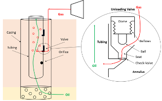
Gas-lifted wells are installed with multiple valves along the wellbore. These valves are pressure operated and controlled by the well pressures and temperatures. This allows the valves to open and close as conditions change.
A typical pressure operated unloading valve consists of a dome charged with gas, usually nitrogen, attached to a bellows which will expand or contract depending on the forces around it. As the bellows expands, the ball attached will move into the seat, closing the valve. A check-valve is also present which ensures that flow only occurs one way.
We can determine whether the valve is open or closed based on a force balance, which is affected by the following factors:
-
Dome pressure: the pressure in the dome is a function of the flowing well temperature, accurate determination of the downhole temperature is the factor that has most influence on whether a valve will be open or closed.
-
Gas Injection pressure at the valve: this can be calculated as the sum of surface injection pressure and the gas hydrostatic.
-
Production pressure at valve depth: this can be calculated as the sum of wellhead pressure, hydrostatic, friction and acceleration (and varies based on WHP, water cut and GOR).
Changing well conditions dictate that the valve opening and closing pressures are dynamic and to determine whether the valves are open or closed need to be re-calculated based on actual well conditions, which vary with time.
Moving the valve from closed to open
From the closed position, the valve will open if the pressure in the casing and tubing, acting on the bellows and port respectively, are able to overcome the pressure within the dome. We can express the conditions at which the valve will open with the following force balance:
Closing Force < Opening Force
PDAb < PpAp + Pi(Ab - Ap)
Where
- PD, dome pressure
- Ab, area of the bellows
- Pp, production pressure at valve depth (i.e. tubing pressure)
- Ap, area of the port
- Pi, injection pressure at valve depth (i.e. casing pressure)
Rather than referring to valve specific port and bellows area, we can combine these into a single geometric term R, capturing the ratio between the port and bellows area
R = Ap / Ab
Dividing everything by the bellows area, the force balance becomes
PD < PpR + Pi(1 - R)
Moving the valve from open to closed
From the open position, the force keeping the valve open is the injection pressure acting across the entire bellows area. This reduces the force balance to
Closing Force > Opening Force
PDAb > PiAb
PD > Pi
Therefore the valve will close as injection pressure drops below the dome pressure. We can then express the opening and closing pressures for an IPO valve as follows
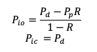
Where Pio = valve opening pressure at depth, Pic = valve closing pressure at depth
Dome pressures of the valves are set at surface in valve testers and are charged at standard conditions of 60 degrees Fahrenheit and at atmospheric pressure (14.7 psia). Using the force balance described previously, we can calculate the dome pressure when injection occurs at standard conditions as
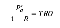
Where:
- P'd : dome pressure at 60 degrees F
- TRO : test rack opening pressure at 60 degrees F
Once installed within the well, the valve will experience much higher temperatures than 60 degrees. The dome pressure will therefore always be higher than the charging conditions at surface and increase proportionally with temperature.
Using a correction factor, , we can convert the dome pressure from 60 degrees F to the conditions at depth

There are a number of different methods for calculating including an equation of state, experimental work by Sage and Lacy [1] for estimating nitrogen compressibility factors and the work of Winkler and Eads [2] on correcting dome pressures at pressures above 1200 psig.
Troubleshooting valve performance
As conditions change within the wellbore, valve opening and closing pressures will also change. A key consideration for troubleshooting valve status is temperature, as this will directly impact the dome pressure and therefore the opening and closing pressure.
For example, a lower production rate will reduce the temperature within the well which will also reduce the pressure within the domes. This will reduce the injection pressure required to close the valve. Changes to fluid composition (i.e. increasing GOR) and increasing water cut will also change the temperature within the wellbore, changing the dome pressure with it.
Using the typical valve parameters for TRO60 and R, we can see in the figure below the proportional relationship between temperature and valve opening and closing pressures.
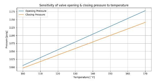
Unless the actual flowing wellbore temperature at valve depth is known, accurate prediction of whether a valve is open or closed is not possible. A 10 deg difference on temperature can vary the valve opening and closing pressures by 20-25psi.
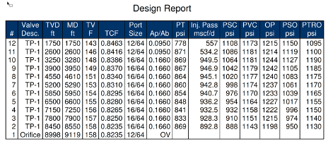
The following design report for a well in the Midland Basin shows much higher flowing temperatures near surface than are usually measured. If the well flowing temperature is lower than the design temperature, the dome pressure and valve opening and closing pressures will also be significantly lower. The indicated surface opening and closing pressures from the initial design are thereby no longer applicable based on current well conditions.
Valve calculations in Pump Checker
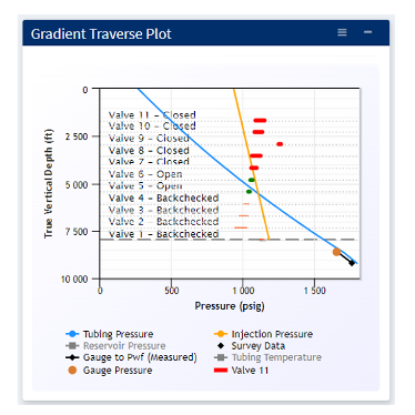
Troubleshooting valve performance becomes easy with Diagnosis within Pump Checker. Using the latest well test, we can calculate actual pressure and temperature along the wellbore using rigorous physics based hydraulic and temperature models. Using the calculated pressure and temperature at the valves in the well is a much more accurate way to determine whether the valves are open or closed compared to using surface opening and closing pressures. Pump Checker calculates the downhole opening and closing pressures automatically for every well test and indicates the values on the Gradient Traverse Plot.
The example below shows how Pump Checker predicts downhole pressure in a well with a downhole pressure and temperature gauge, providing verification of the ability to calculate pressure and temperature along the wellbore. Using these outputs, we can confidently estimate the status of the valves. The model shows that injection is occurring shallow of the deepest point with possible multi-pointing, with injection likely occurring at valves 5 and 6.
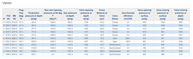
We can further diagnose the latest valve performance with in-depth valve results in Pump Checker. Using these results, we can see the estimated force balance at the valve, gas flowrate across the valves and the opening closing pressure at both surface and downhole conditions. The surface opening and closing pressures displayed in Pump Checker are recalculated on a per test basis based on actual operating conditions.
Conclusion
Gas lift systems are at their most efficient when injection is as deep as possible in the well. To determine the injection depth, we require accurate estimates of conditions within the wellbore. In this regard, temperature is critical when estimating the valve opening and closing pressures. Using Pump Checker, valve opening and closing pressures are accurately and dynamically updated as conditions change over time, enabling troubleshooting of valve status
References
- Sage, B.H. – Lacey, W.N.: “Thermodynamic Properties of the Lighter Paraffin Hydrocarbons and Nitrogen.” API Monograph No. 37. American Petroleum Institute, 1950.
- Winkler, H.W. – Eads, P.T.: “Algorithm for More Accurately Predicting Nitrogen-Charged Gas-Lift Valve Operation at High pressures and Temperatures.” Paper SPE 18871 presented at the Production Operations Symposium held in Oklahoma, City, March 13-14, 1989.